
Sommaire :
•Ancien projet et objectifs
•Cahier des charges
•Fonctionnalités/Réalisation
-Distributeur de pièces
-Bras robotisé
•Matériel
•Programme des différents systèmes
-Arduino
-NodeRed
-Staubli
-Cognex
•Problèmes rencontrés
•Conclusion / Objectifs accomplis
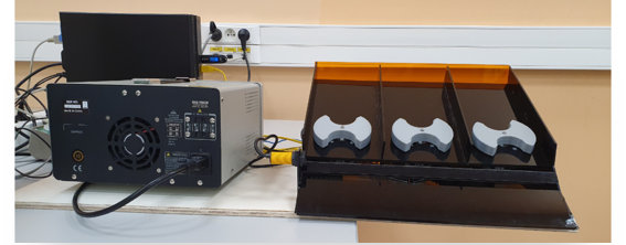
1) Présentation de l’ancien projet :
Notre projet est basé sur l’amélioration d’un projet d’étudiants en DUT GEII de l’année précédente (Figure 1). Il consiste à créer une chaine automatisée afin de faire une démonstration lors des journées portes ouvertes de l’IUT. Le principe est simple, un automate dépose une pièce cylindrique d’une couleur quelconque sur un tapis roulant de manière aléatoire, une caméra envoie l’information de la couleur et de la position de la pièce au bras robotisé qui se chargera de déplacer la pièce pour la remettre dans le distributeur. Nous avons choisis d’améliorer ce projets, car le précédent distributeur automatisé utilisait des moteurs pas à pas, pilotés à l’aides de modules spécifique et d’une Arduino Mega (ce qui est très couteux).
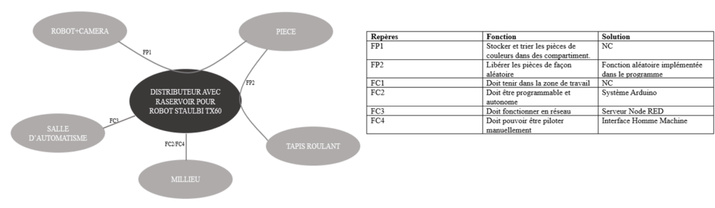
2) Cahier des Charges
Une fois que les besoins étaient définis nous avons pu établir un cahier des charges (Figure 2). Les deux fonctions principale sont:
-distribuer les pièces de manière aléatoire.
-stocker et trier ces pièces dans des compartiments.
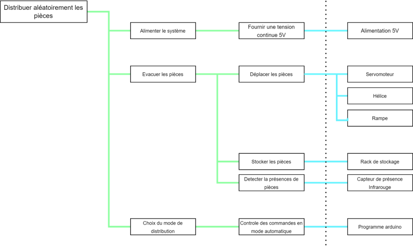
3) Définition des fonctionnalités
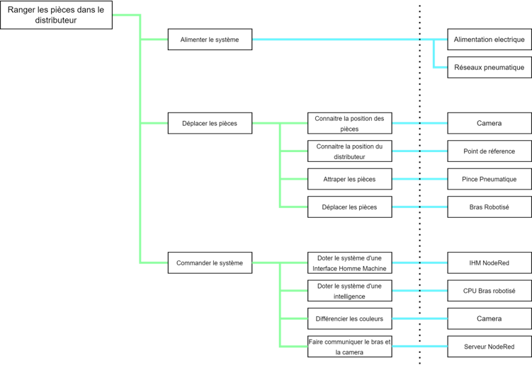
A l’aide du cahier des charges nous avons pu définir des diagrammes FAST, afin de décrire toutes les fonctionnalités de notre projet (Figure 3.1 et 3.2).
Notre projet contient deux systèmes:
Partie distributeur de pièces (Figure 3.1):
Partie robot et caméra industrielle: (Figure 3.2):
4) Matériel
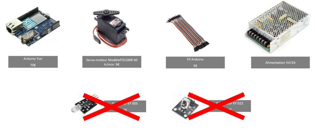
De ces différentes fonctionnalités, nous avons fait une liste de matériel, pour la création du distributeur de pièces (Figure 4):
Nous avons choisi d’utiliser un Arduino Yun car la programmation de petit systèmes embarqué comme celui-ci est très simple, de plus le Yun possède une interface Linux ce qui nous permettrait éventuellement de le relier à un serveur Node Red. Nous utilisons ces Servomoteurs, car ils ont un couple largement suffisant pour déplacer les pièces. Ils sont aussi très facilement pilotables avec la carte Arduino, car ils ne nécessitent pas de module spécifique. En revanche les capteurs de présence pièce initialement prévu n’ont pas été gardé car jugé trop encombrant pour ce qu’ils apportaient au projet.
5) Partie programmation
A) Programme Arduino
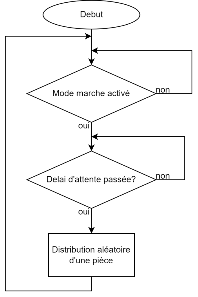
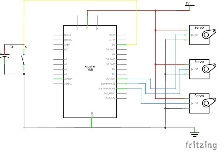
Le programme Arduino permet de distribuer une pièce de manière aléatoire à chaque fois que le délai d’attente a été passé. Nous utilisons la fonction rand() pour cela. Le programme a été conçue de manière modulaire, pour rajouter simplement des capteurs ou une nouvelle couleur de pièce c’est pour cela que tout est conçu sur des définitions de tableaux. Le pilotage des Servomoteurs se fait à l’aide d’une fonction ce qui permet de ne pas changer tout le programme en cas de changement du système de pilotage des actionneurs (Figure 5.1 et 5.2). On a aussi programmé un bouton poussoir, pour mettre en marche ce système. Pour éviter les problèmes de rebonds avec ce bouton, nous l’avons mis en parallèle avec une capacité (Figure 5.3).
Synoptique Arduino (Figure 5.1):
Programme Arduino (Figure 5.2):
#include <Servo.h>
#define pin_onoff 2

int temp_rotation = 420;
int pin_capteur[] = {7, 8, 7};
int valeur_pwm[][3] = {{700, 1480, 2300}, {700, 1485, 2300}, {700, 1475, 2300}};
int pin_moteur[] = {9, 10}; //11 et pin pwm obligatoire
int nbmoteur = (sizeof(pin_moteur)) / 2;
int temp_distribution = 1000;
unsigned long temp;
int distro;
bool onoff = 1;
Servo monservo;

void setup()
{
  Serial.begin(9600);
  for (int i = 0; i < nbmoteur ; i++ )
  {
    pinMode(pin_capteur[i], INPUT);
    pinMode(pin_moteur[i], OUTPUT);
  }

  //définition boutons IHM
  pinMode(pin_onoff, INPUT_PULLUP);
  pinMode(13,OUTPUT);
  attachInterrupt(digitalPinToInterrupt(pin_onoff), etat, FALLING);
  temp = millis(); //enregistre le temps écouler
  Serial.print("Durer de l'initialisation :");
  Serial.println(temp);
  Serial.print("NBMOTEUR :");
  Serial.println(nbmoteur);
}

void loop()
{

  if (onoff == 1) {
    if ((temp + temp_distribution) <= millis())
    {
      distro = random(0, nbmoteur);
      /*while (digitalRead(pin_capteur[distro]) == 0)
        {
        distro = random(0, nbmoteur);
        }*/
      lancement_piece(distro);
      temp = millis();
    }
  }
}


//fonction gérant le sens de rotation du servo moteur
void lancement_piece(int numero_moteur)
{
  moteur(numero_moteur, valeur_pwm[numero_moteur][0]);
  unsigned long temp = millis();
  while ((temp + temp_rotation) >= millis()) {}
  /*moteur(numero_moteur, valeur_pwm[numero_moteur][2]);
  temp = millis();
  while ((temp + temp_rotation) >= millis()) {}*/
  monservo.detach();
  //moteur(numero_moteur, valeur_pwm[numero_moteur][1]);
}

//fonction gérant le sens de rotation du servo moteur
void moteur(int numero_moteur, int valPWM)
{
  Serial.print("N° moteur:");
  Serial.print(numero_moteur);
  Serial.print("    Valeur PWM:");
  Serial.print(valPWM);
  Serial.print("    N° Pin Moteur");
  Serial.println(pin_moteur[numero_moteur]);
  monservo.attach(pin_moteur[numero_moteur]);
  monservo.writeMicroseconds(valPWM);

}
void etat() {
  temp = millis();
  if (100 + temp >= millis()) {
    onoff = !onoff;
    digitalWrite(13,onoff);
    //Serial.print("Etat On/Off : ");
    //Serial.println(onoff);
  }
}
Schéma électrique de l’Arduino:
Le programme est téléchargeable ici
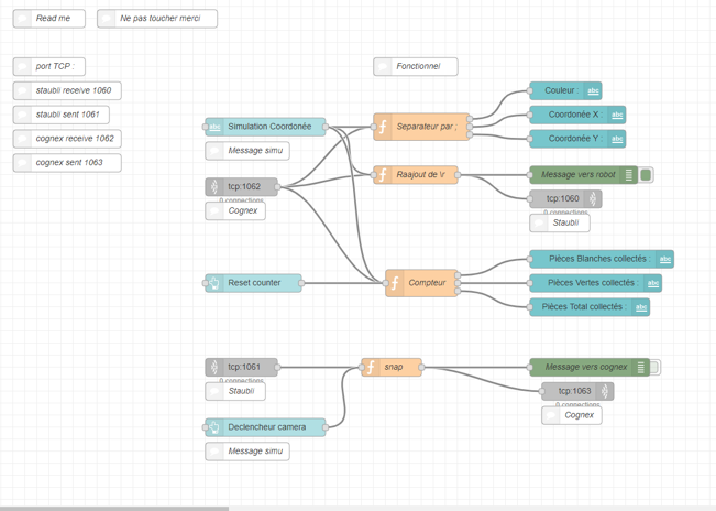
B) Nodered
Synopsis global du transfert des données entre les différents systèmes (Figure 5.4):
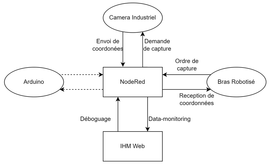
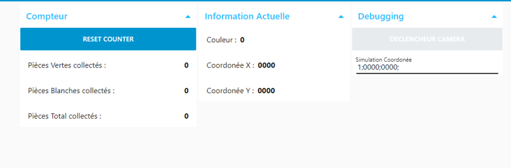
Le serveur Node Red formate les données selon le destinataire et ajoute une interface web permettant ainsi des contrôles manuels.
Nous avons aussi défini aux travers de ce serveur 4 ports: Staubli receive « 1060 »; Staubli sent « 1061 »; cognex receive « 1062 »; cognex sent « 1063 » , ils permettent de faire la liaison entre la caméra et le robot (Figure 5.5).
Le fichier à importer pour recréer le serveur NodeRed est disponible ici.
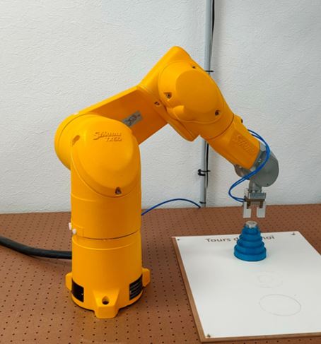
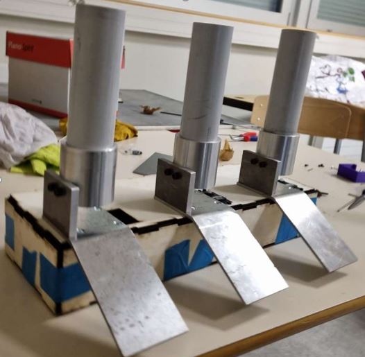
C)Le Robot Staubli
Le robot (Figure 5.6), envoie des demandes de photo à la caméra jusqu’à la présence de pièces. Il attend les coordonnées ainsi que la couleur de la pièce, que la caméra va lui rendre. Une fois les données retournées, le robot ira saisir la pièce aux coordonnées indiquées et la posera au bon endroit (selon la couleur de cette pièce) (Figure 5.7 et 5.8).
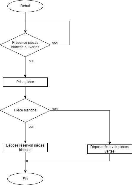
Synoptique du programme (Figure 5.7):
cls()
  prisetemp=prise
  deposetemp=depose
  deposetemp2=depose2

  // port receive 1060
  //port send 1061
  //S="1;300;500"


  while true
    S="0;0000;0000"
    mult=0
    mult2=0
    couleur=0
    xpos=0
    ypos=0
    putln("Debut ")
    //  cameraSend=toString("snap",i)
    //  S=cameraReceive


    do
      clearBuffer(cameraReceive)
      clearBuffer(cameraSend)
      movej(j2,pince,rapide)
      cameraSend=toString("send",i)
      S=cameraReceive
      couleur=asc(S,0)-48

      put(couleur)
      putln("fin")
      delay(0.5)
    until(couleur>0)


    //teste le signe des coordonnées

    if asc(S,2)==45
      mult=-1
    endIf

    if asc(S,2)==48
      mult=1
    endIf

    if asc(S,7)==45
      mult2=-1
    endIf

    if asc(S,7)==48
      mult2=1
    endIf

    couleur=asc(S,0)-48

    xpos=mult*(asc(S,3)-48)*100+(asc(S,4)-48)*10+(asc(S,5)-48)
    put(xpos)
    put(" ")

    ypos=mult2*(asc(S,8)-48)*100+(asc(S,9)-48)*10+(asc(S,10)-48)
    put(ypos)

//gère le point de prise en fonction des coordonnées données par la cognex

    prisetemp.trsf.x=prise.trsf.x+xpos
    prisetemp.trsf.y=prise.trsf.y+ypos

    priseapp=appro(prisetemp,{0,0,-30,0,0,0})
    deposeapp=appro(deposetemp,{0,0,-30,0,0,0})
    deposeapp2=appro(deposetemp2,{0,0,-30,0,0,0})

    movej(j2,pince,lent)
    movej(priseapp,pince,rapide)
    movel(prisetemp,pince,lent)
    close(pince)
    movel(priseapp,pince,lent)

    //gère le point de dépose en fonction de la couleur
    if couleur==1

      movej(deposeapp,pince,rapide)
      movel(deposetemp,pince,lent)
      open(pince)
      movel(deposeapp,pince,lent)

    endIf

    if couleur==2

      movej(deposeapp2,pince,rapide)
      movel(deposetemp2,pince,lent)
      open(pince)
      movel(deposeapp2,pince,lent)
    endIf

    movej(j2,pince,rapide)
    putln(" fin")

  endWhile
  waitEndMove()

//Figure 5.8: Programme du robot
Le fichier du projet Staubli est disponible ici.
D) La caméra COGNEX
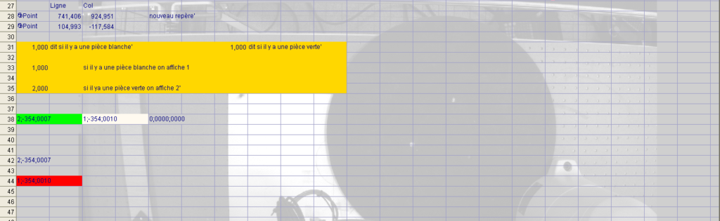
La caméra attend la demande d’une photo du Robot, s’il n’y a pas de pièces, alors la caméra reprend une photo jusqu’à la présence d’une pièce. Nous avons utilisé une syntaxe spécifique qui est commune au robot et à la caméra, pour la transmission de message (Figure 5.8).
| Syntaxe | 0; | 0000; | 0000 |
| Explication | Couleur de la pièces (0 si absent; 1 si blanc; 2 si vert) | Coordonnées x (Premier caractère = ‘-‘ si Coordonnées négative ou ‘0’ si coordonnée positive) | Coordonnées y (Premier caractère = ‘-‘ si Coordonnées négative ou ‘0’ si coordonnée positive)) |
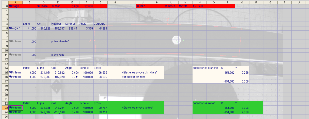
Programme de la caméra cognex (Figure 5.9) :
La détection des pièces se fait à l’aide de la fonction « TrainPatMaxPattern »
Pour différentier deux couleurs (le vert et le blanc dans notre cas), on joue sur la luminosité.
Cela nous permet de différentier parfaitement la couleur verte de la blanche. Cependant, il arrive souvent qu’une pièce blanche soit détectée à la fois comme verte et blanche. C’est pour cela que quand une pièce est détectée comme verte et blanche, on priorise le blanc.
On a aussi créé un point de référence à l’aide de la fonction « Point », qui est le même pour le TX 60.
Enfin, toutes les coordonnées sont converties en millimètre pour pouvoir être exploitées par le robot.
Le fichier du projet NodeRed est disponible ici.
6)Problèmes rencontrés
Les problèmes majeurs que nous avons rencontré sont :
– Chaque servomoteur a une valeur PWM différentes pour les mêmes mouvement (On as dû affiner ces valeurs par expérimentation).
– Les servomoteurs ont un courant de consommation crête bien plus élevé que ce que la datasheet donnait (1,1 A contre 1,6 A dans la réalité) ce qui créait des chutes de tension et redémarrait l’Arduino, on a donc dû surdimensionner l’alimentation.
– Les axes x et y de la caméra ne sont pas aligné avec les axes du bras robotisé ce qui empêche la bonne prise de pièces. Ce problème vient du robot Staubli, qui a son axe Y non perpendiculaire à la table.
Pour résoudre ce problème, il faut modifier le programme du Robot et mettre ceci dans les coordonnées du point de prise :
X’=X.cos(T) – Y sin(T)
Y’=X sin(T) + Y cos(T)
Ici X et Y sont les coordonnées envoyées par la caméra et T est l’angle d’écart qu’il y a entre le repère de la caméra et le repère du robot.
– La caméra positionnée au-dessus du robot est une caméra noire et blanc ce qui empêche la différenciation de plus de deux couleurs.
7) Conclusion
Ce projet fut très intéressant, il nous a permis d’appliquer les connaissances de In-sight et Staubli vu en cours directement sur un projet concret. En revanche la partie NodeRed fut une complète découverte !!
Cependant certain point reste à améliorer :
– Le système Arduino devrait être pilotable à travers l’interface web du serveur NodeRed.
– Intégrer la partie Arduino dans la maquette des DUT GMP, vu que cette maquette ne fut terminée qu’après nos séances de projets (Figure 7).
– Utiliser un condensateur pour éviter les chutes de tension plutôt que de surdimensionner l’alimentation.
– Utiliser une caméra couleur pour différencier plus de deux Couleurs.
– Calibrer les axes de la caméra et du robot TX 60.
Projet réalisé par :
– Erwan LAROPPE
-Louis MATHIS
Pour les curieux l’archive complète de notre projet est disponible ICI :
https://drive.google.com/drive/folders/1frOojPXsxAnuPceLYTKd4kq09x3KXn2p?usp=sharing